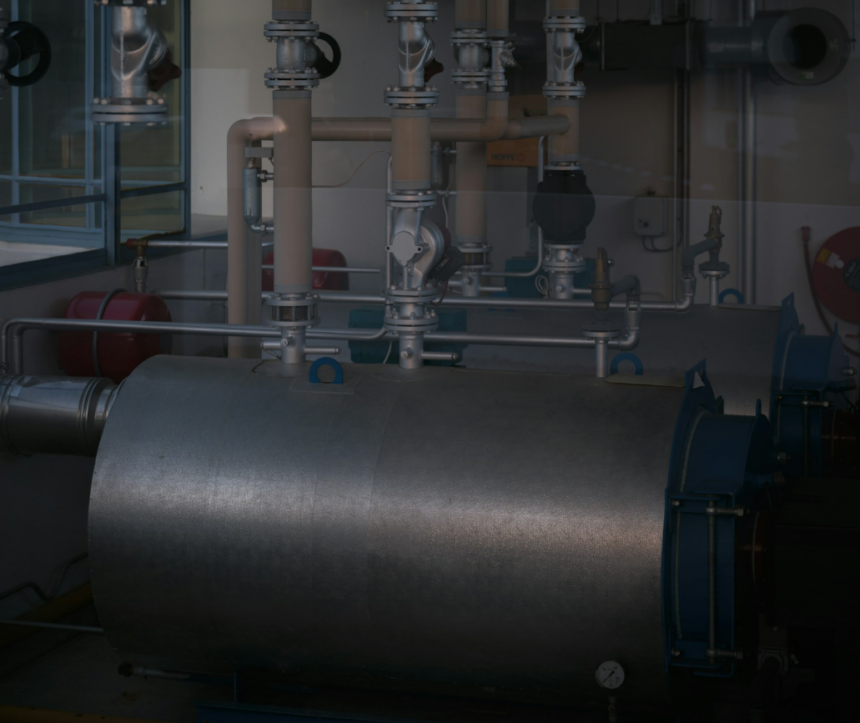
When several boilers, pumps and heating zones share the same pipework, they start working against each other, causing noise, short-cycling and cold rooms. A low loss header solves this by separating the circuits hydraulically. This guide explains how it works, when a system needs one and how to size and install it correctly.
Walk into the plant room of a school, an office block or a large house and you will often see a short, fat vertical tube sitting between the boilers and the pipework that feeds the building. It looks unremarkable, but it solves one of the most common problems in wet heating design. That tube is a low loss header, and understanding when it is needed can save a lot of noise, wasted energy and frustrated callbacks.
The problem: circuits that fight each other
A simple domestic system has one heat source, one pump and one circuit. The pump pushes water through the boiler and out to the radiators, and everything moves at the same rate.
Larger systems are rarely that tidy. A typical commercial installation might have two or three boilers, each with its own pump, feeding several zones: radiators upstairs, underfloor heating downstairs, an air handling unit and a hot water cylinder. Each zone has its own pump and its own demand, which changes through the day as valves open and close.
When all those pumps share the same pipework directly, they interfere with one another. A powerful zone pump can drag water backwards through an idle boiler. A boiler pump can force flow through a zone that should be off. Flow rates through the boilers swing up and down, which upsets their controls and can trip high-limit thermostats. The symptoms are familiar to any heating engineer: noisy pipes, rooms that will not heat, boilers short-cycling and pumps wearing out early.
The solution: hydraulic separation
Hydraulic separation means splitting the system into a primary circuit, which carries heat from the boilers or heat pump, and one or more secondary circuits, which deliver it to the building. Each circuit is driven by its own pump, and the two are joined through a component with very low resistance to flow.
A low loss header is that component. Because its diameter is much larger than the pipes connected to it, water slows down sharply inside it and the pressure difference between top and bottom is tiny. In practice, this means the primary pumps and the secondary pumps no longer push against each other. Each side can run at the flow rate it needs, and the header absorbs the difference.
Three flow situations show how this works:
- Balanced flow: primary and secondary flow rates match, so hot water passes straight across the header and very little moves vertically inside it.
- Primary flow greater than secondary: some hot water drops down through the header and returns to the boilers. This often happens when zones close in mild weather.
- Secondary flow greater than primary: some cooler return water rises and mixes into the flow, so the building receives water a few degrees cooler than the boilers produce.
Good design aims for the primary flow to be equal to, or slightly higher than, the secondary flow, so the building always gets full flow temperature.
When a low loss header makes sense
Not every system needs one. A single boiler with a single heating circuit is usually better served by simple, well-balanced pipework. A header becomes the right choice when one or more of these apply:
- Multiple heat sources: two or more boilers, or a boiler combined with a heat pump, each with its own pump
- Multiple pumped zones: separate circuits for radiators, underfloor heating, air handling units or calorifiers
- Low water content boilers: many modern wall-hung condensing boilers need a guaranteed minimum flow rate that a varying system cannot provide
- Heat pumps: they need steady flow through the outdoor unit regardless of what the zones are doing
- Retrofits: connecting a new boiler to an old system whose pipework and pumps are of uncertain size
Specialist suppliers publish useful technical pages on this. A good example is this overview of what a low loss header does, which also shows the common connection layouts and sizes side by side, handy when comparing options for a specific plant room.
Sizing and installation basics
A header that is too small loses its benefit, because water does not slow down enough for the circuits to separate. Designers usually work from the total primary flow rate and select a header with low internal velocity, commonly around 0.1-0.2 m/s. A widely used rule of thumb is that the header diameter should be roughly three times the diameter of the largest connected pipe, though manufacturer data should always take priority.
A few practical points help the header do its job:
- Mount it vertically, with primary connections on one side and secondary on the other
- Keep flow connections near the top and return connections near the bottom
- Fit an automatic air vent at the top and a drain valve at the bottom
- Choose a model with built-in air and dirt separation where possible, since the slow water speed inside the header is ideal for dropping out debris and releasing microbubbles
- Place sensors carefully: the boiler controls should read the temperature on the secondary flow, after the header, so they respond to what the building actually receives
Multi-tapping and distribution headers take this a step further by combining separation with a manifold, giving each zone its own flow and return connection in one compact unit. In crowded plant rooms, that can save a surprising amount of pipework and installation time.
Common mistakes
The most frequent error is fitting a header and then running the secondary pumps harder than the primary ones. The result is cooler flow to the building, which on condensing boilers can push up return temperatures and reduce efficiency at the same time. Matching pump settings during commissioning, and checking temperatures on both sides of the header, avoids this.
Another is treating the header as a fix for poor design elsewhere. It will not cure undersized pipes, missing balancing valves or a badly located expansion vessel. It works best as one part of a properly designed system.
The bottom line
A low loss header is a simple component with a precise job: letting different circuits run at their own pace without interfering with each other. In any system with several heat sources or pumped zones, it turns a set of competing pumps into a stable, controllable whole, and that stability shows up as quieter pipes, steadier boilers and lower running costs.